What is Graphiant’s Local Web Server?
Graphiant’s Local Web Server provides you direct access to your Edge.
The local web server is key in helping you:
Set the WAN configuration to get your Edge connected to the Graphiant Portal when DHCP is not available
Troubleshoot connection issues when not connected to the Graphiant Portal
This article covers onboarding your Graphiant Edge, including setting the WAN configuration to connect your Edge to the Graphiant Portal.
For information on troubleshooting connection issues, see Troubleshooting Using the Local Web Server.
How Do I Locate Graphiant’s Local Web Server
Ensure that you are connected to your Graphiant Edge through the last (local management) port.
Note:
You must be on the same network as the local management interface.
The Graphiant Local Web Server is only reachable via your web browser.
Point your browser to: https://192.168.1.1
You will receive a security warning due to Graphiant using a Self-Signed Certificate; accept to connect.
You will see the Graphiant Local Web Server Portal.
Simply click ‘Login’ to access your edge.
If your Graphiant Edge has previously been connected to the Graphiant Portal:
You will need to enter the password you configured there.

You will now be in the Graphiant Local Web Server for your Edge.
Note:
When your Edge comes up and doesn’t connect to the Portal, it will enable a DHCP server on its management interface to give you an IP address.
As soon as the connection to the Graphiant Portal comes up, the Edge will disable that DHCP server but you can still access the management interface via https://192.168.1.1 by setting a static IP address on your laptop.
When onboarding your Graphiant Edge, you will utilize these sections of the Local Web Server:
Dashboard: Contains the configuration summary information for your Edge
Interface & Routes: Allows you to configure interfaces, WAN circuits, and static routes
Review Changes: The review and application of any configuration change to your Graphiant Edge
‘Reboot Device’ and ‘Logout’ are available at all times at the top of your screen.
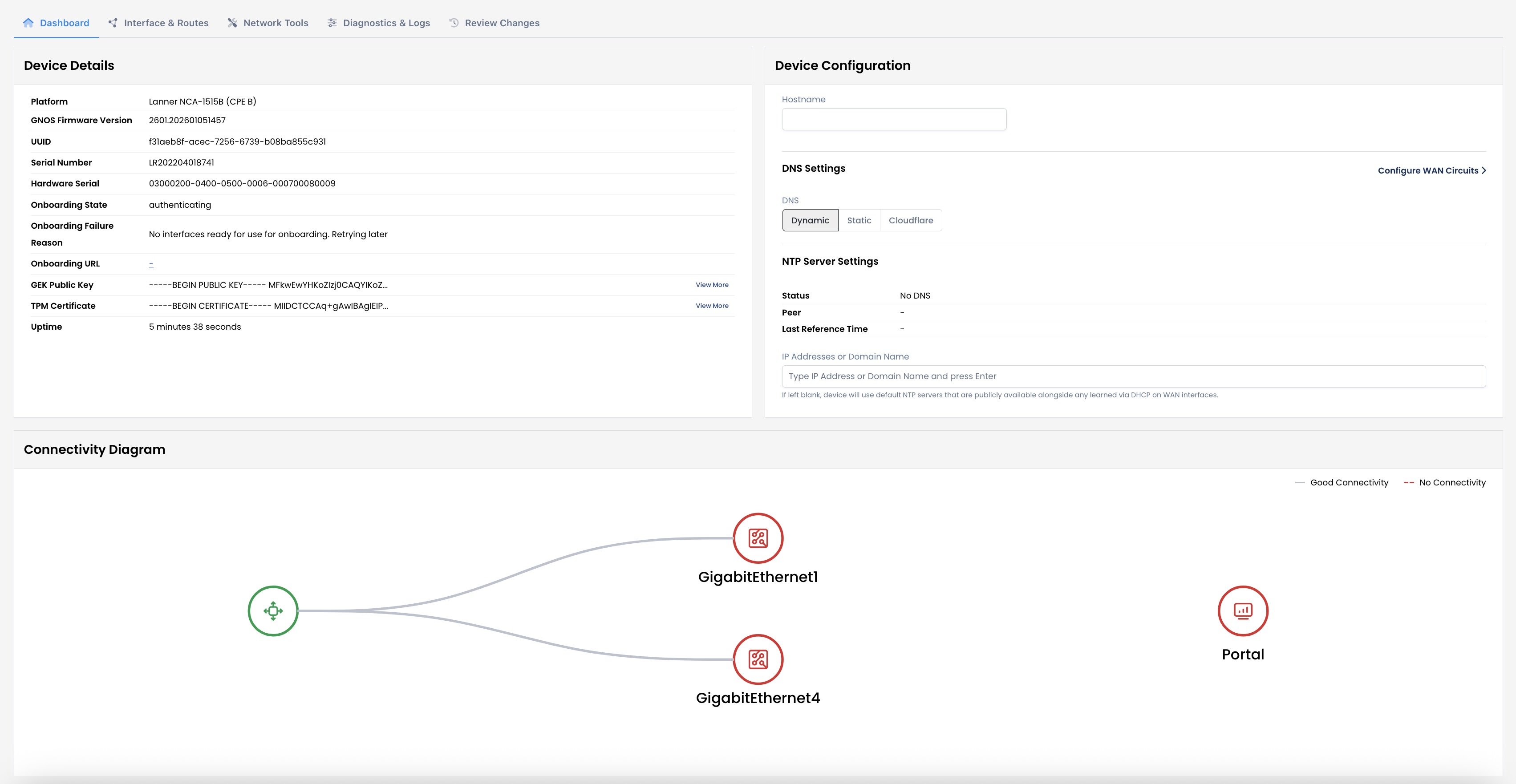
Local Web Server Dashboard Summary
The landing page for the local web server is the Dashboard.
This gives you all of the following:
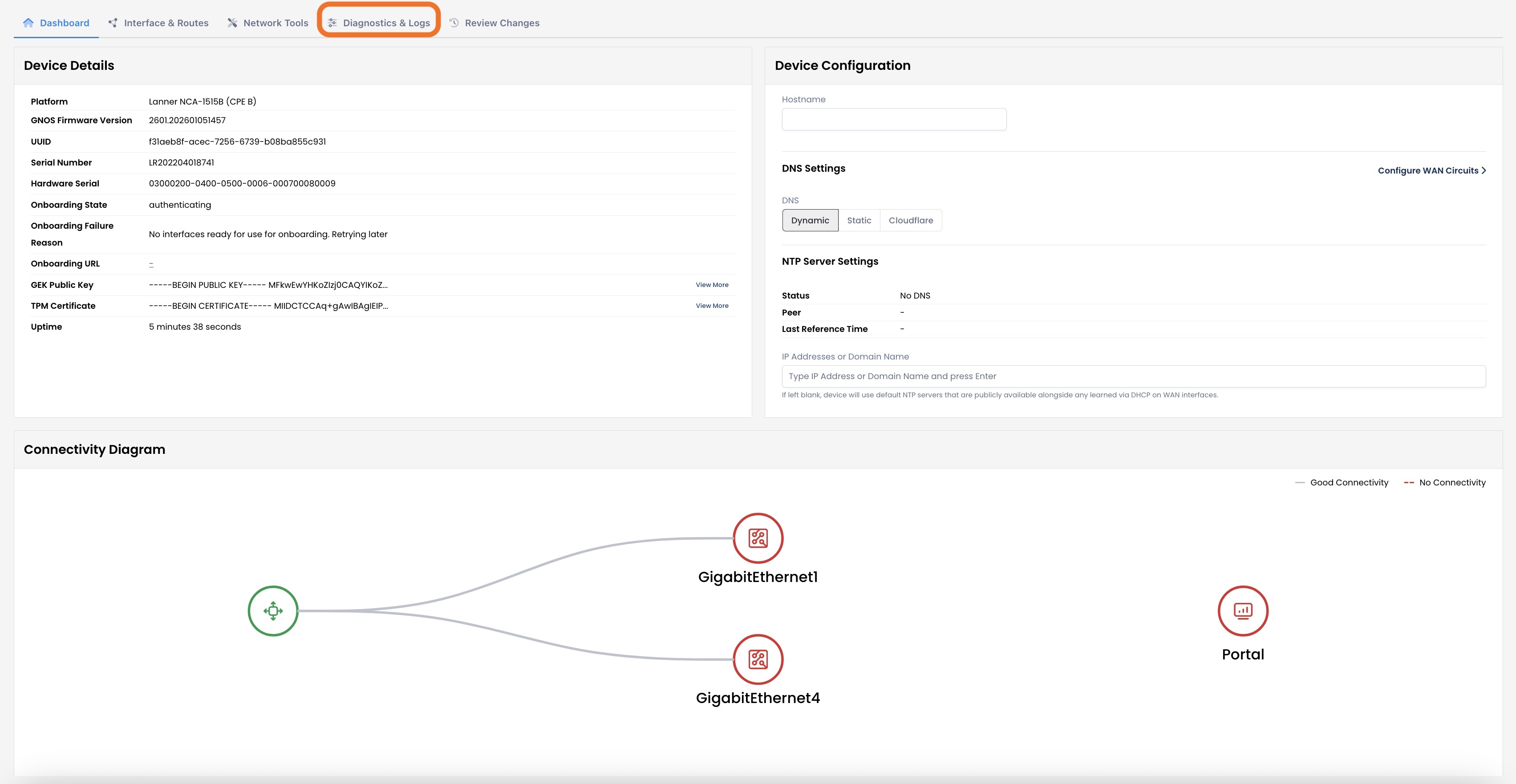
Device Details
Platform
Graphiant Network Operating System Firmware Version
UUID
Serial Number
Hardware Serial
Onboarding State: Where the Edge is within it’s onboarding process
Onboarding Failure Reason: Should an onboarding attempt have been made, the reason will appear here
Onboarding URL: If onboarded, this will show the address your Edge uses to connect to the Graphiant network
GEK Public Key (Graphiant Enrollment Key): Public key that allows this device to securely authenticate with Graphiant services
(Click ‘View More’ to see the full key)
TPM (Trusted Platform Module) Certificate: Hardware-based certificate that securely proves this device’s identity during onboarding
(Click ‘View More’ to see the full certificate)
Uptime: The length of time the connection to the local web server has been active
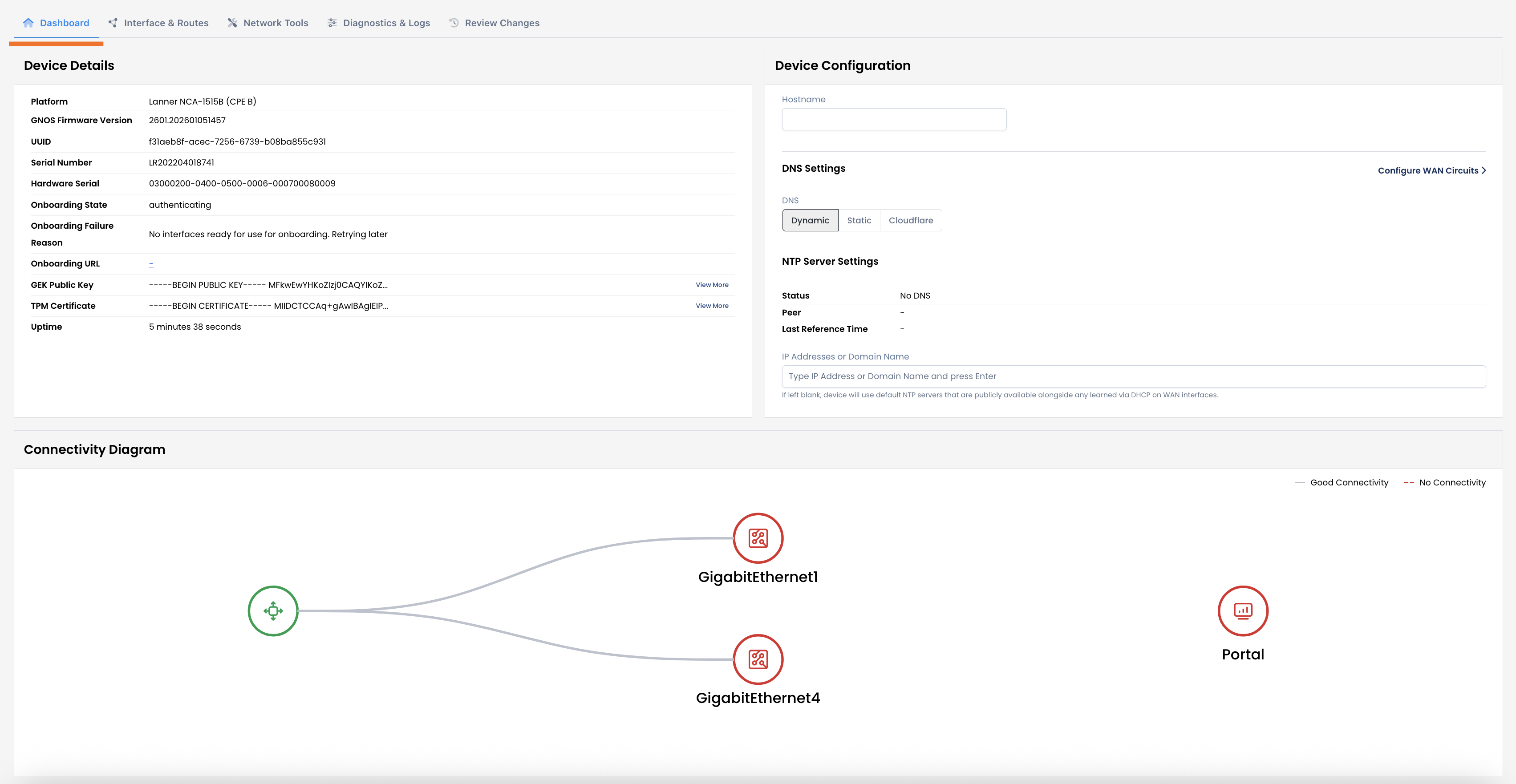
Device Configuration
Hostname: Reflects the name of your Edge that is assigned when connected to the Graphiant Portal; i
This field is uneditable
DNS Settings: Whether you are utilizing a Dynamic (DHCP) or Static DNS, or if you prefer to use Cloudflare
If ‘Static’ is selected: You will be asked to provide the primary and secondary IPv4/IPv6 addresses.
NTP Server Settings: You can connect this Edge to an NTP server for accurate and consistent timestamps.
Perform the following process for as many NTP Servers as you would like to add to your configuration:
Note:
Using multiple NTP servers will provide a higher level of accuracy and reliability v/s using a single NTP server.
IP Address or Domain Name: Enter the IP address or domain name of the NTP Server which your device will contact for the exact time.
Hit <Enter>.
From here, you can select to go directly to configure your WAN circuits if desired, without going tab by tab.
Connectivity Diagram
The connectivity of your device to the Graphiant Portal is shown here.
As this Edge is not yet onboarded:
The Connectivity Diagram is not yet showing green to the Graphiant Portal.
Interfaces & Routes
This tab houses information about:
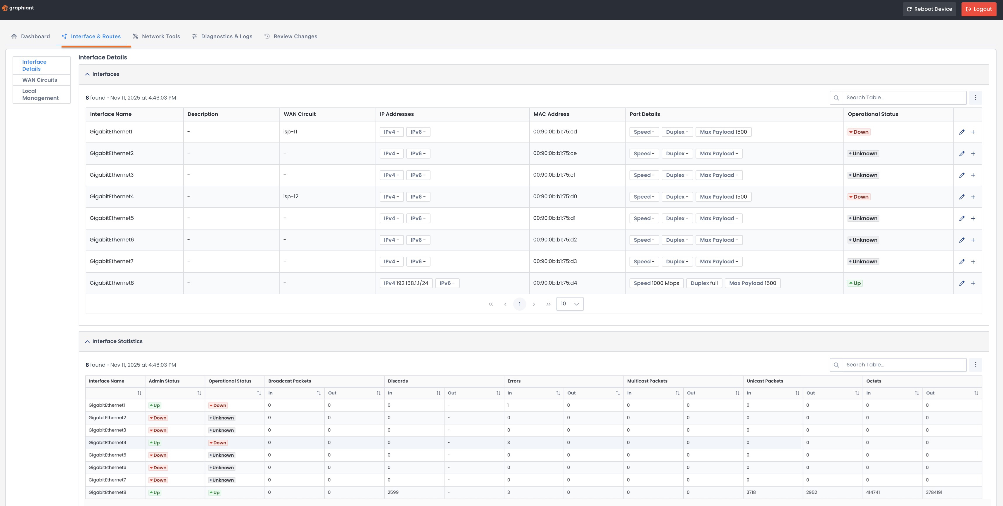
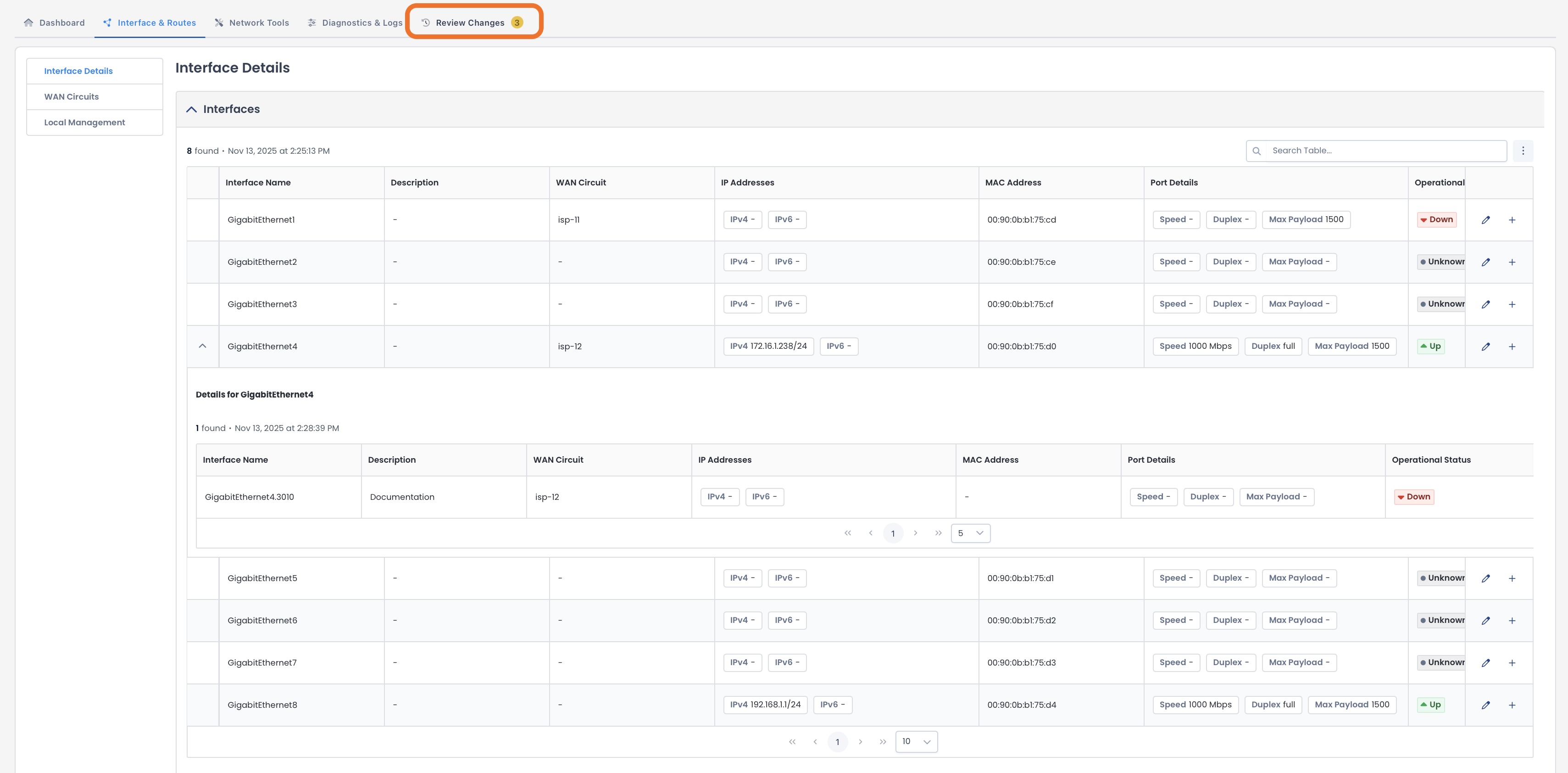
Interface Details
The Interface Details page houses:
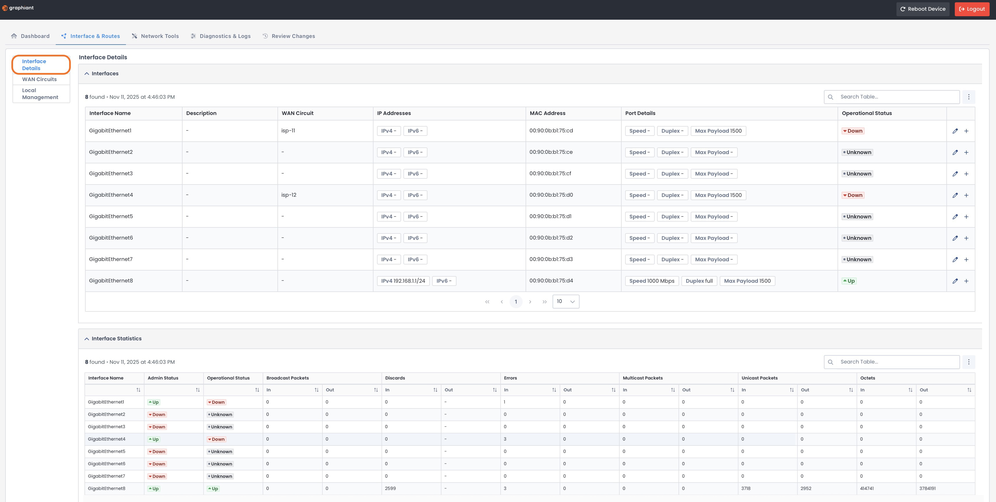
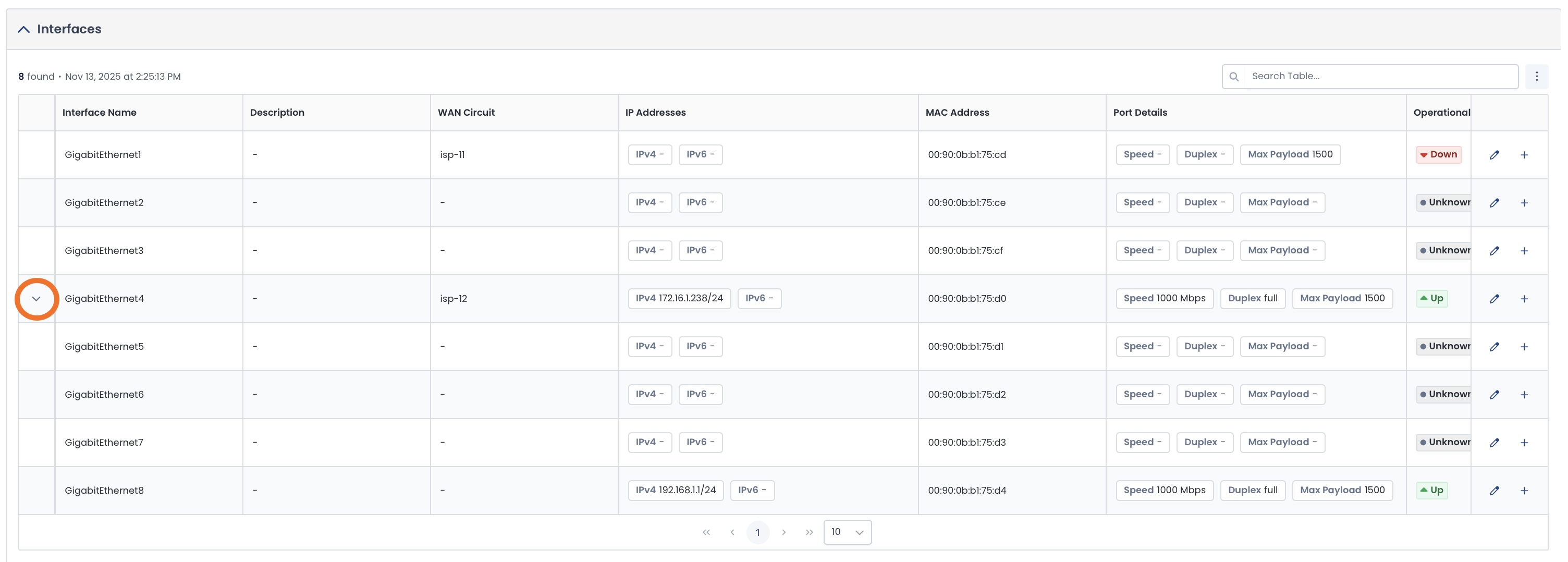
Interface Table
This table provides you with the following information:
Interface Name: Which interface on your Edge
Description: Your description of the interface for ease of reference
WAN Circuit: That is assigned to the interface
By default:
isp-11 = the first WAN interface
isp-12 = the second WAN interface
IP Addresses: Belonging to the interface
MAC Address: Physical address of the interface
Port Details:
Speed: Maximum rate data can travel through the interface
Duplex: Type of communication, either:
Half-Duplex: Two-way communication
Full-Duplex: One-way communication
Max Payload: Largest amount of data that can be transmitted without needing fragmentation
Operational Status: Whether the interface can transmit and receive data packets successfully
You also have the ability here to:

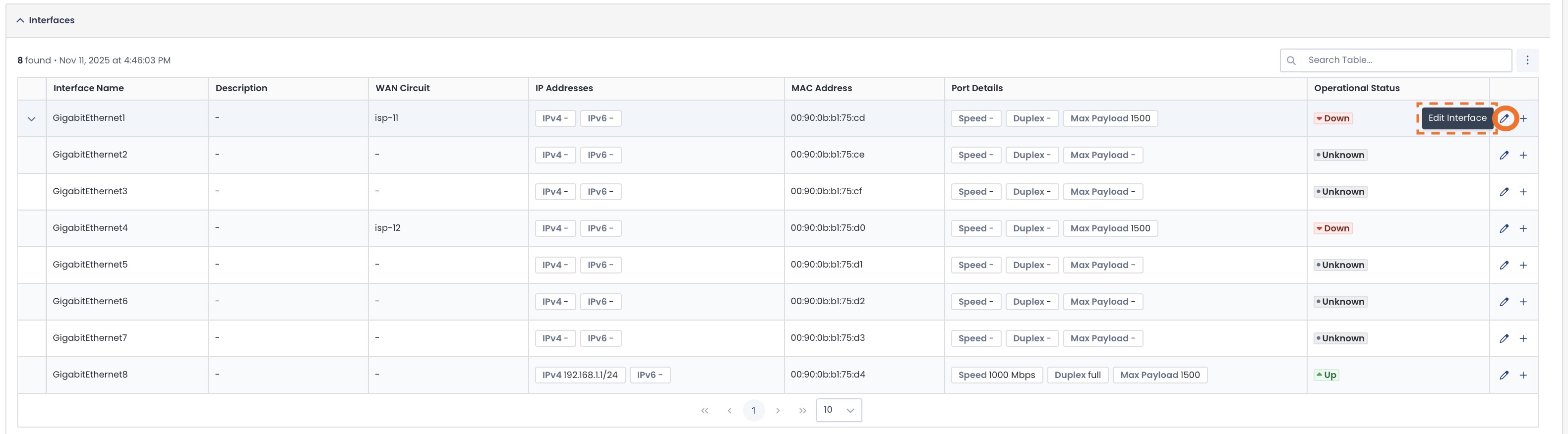
Editing an Interface
To edit an interface, click the pencil icon to the right of the interface to be edited.
If the interface has a WAN circuit assigned to it, the fields you can edit will be:
Interface Description: Your description of the interface for ease of reference
WAN Circuit: Remove the current WAN circuit, or choose a different one from the dropdown
If Static IP Address:
IP Address / Subnet Mask
Gateway: For this network
Note: A DHCP Route will not be editable.
Make the desired changes; click ‘Save’.

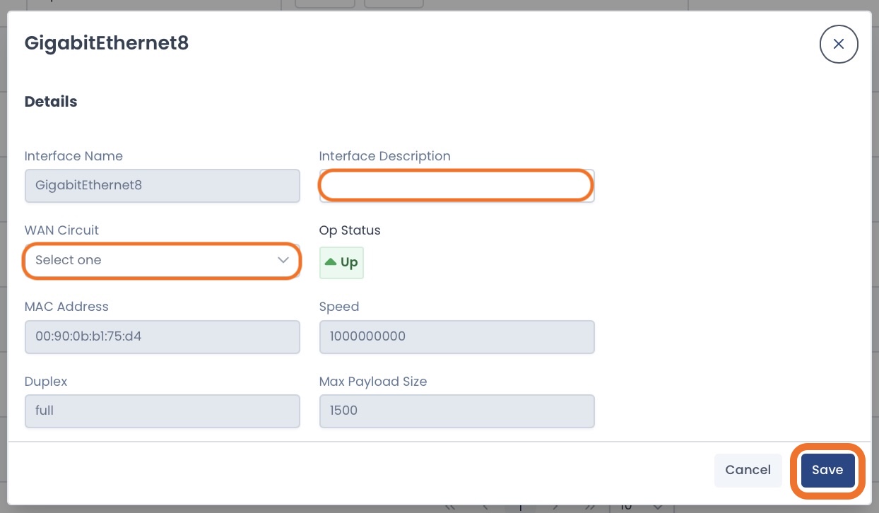
If the interface does not have a WAN circuit assigned to it, the fields you can edit will be:
Interface Description: Your description of the interface for ease of reference
WAN Circuit: From the dropdown, select the WAN circuit you would like to assign to the interface
Make the desired changes; click ‘Save’.
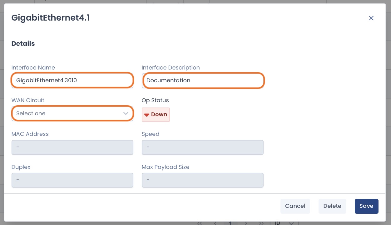
Adding a Subinterface
To add a subinterface, click the [+] icon to the right of the interface that will be its parent.

Complete the following fields:
Interface Name: This is auto-populated, but the subinterface identifier value (after the parent interface number) is editable for your convenience
Interface Description: Your description of the subinterface for ease of reference
WAN Circuit: From the dropdown, select the WAN circuit you would like to assign to the subinterface
The subinterface cannot have the same WAN circuit assigned to it as its parent interface.
After you have selected a WAN circuit, the model will extend for the route options.
Select your route as required.
If Static IP Address:
IP Address / Subnet Mask
Gateway: For this network
Note: A DHCP Route will not be editable.
Click ‘Save’.

The parent interface will now show a carat indicating a subinterface is present.
Click the carat to view details.
The subinterface configuration information is shown here.

Follow the instructions for reviewing and applying changes.
The new subinterface will be configured on your Edge, and now appear in the Interface Statistics table.
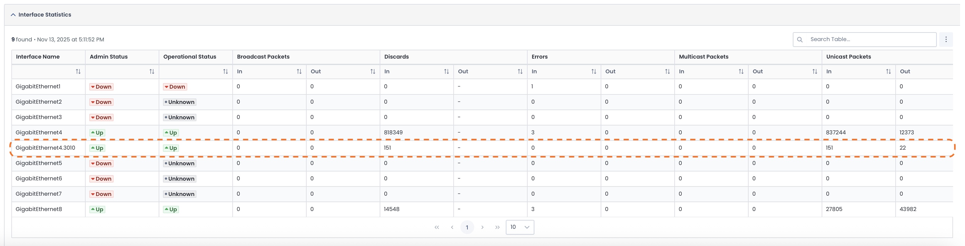
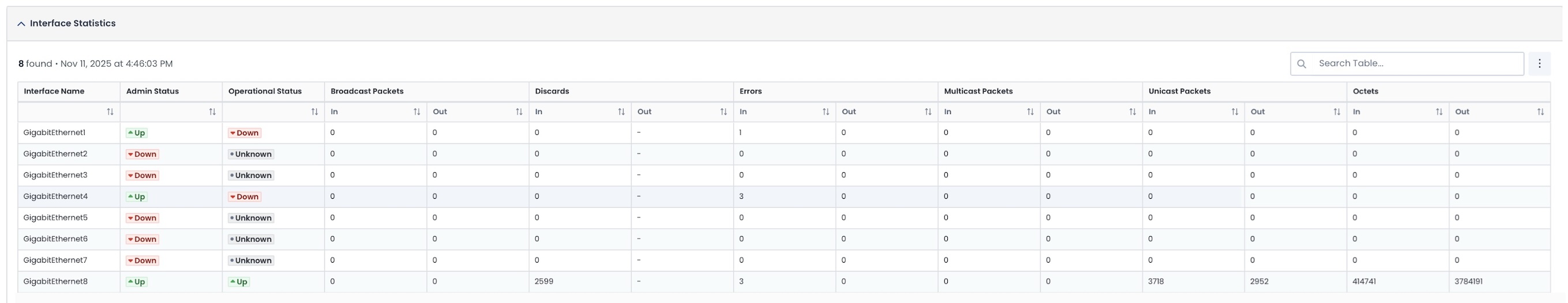
Interface Statistics
The Interface Statistics table shows you the following:
Admin Status: The configured state of the interface by an administrator
Operational Status: Whether or not the interface is connected
Broadcast Packets (In/Out): Packets sent to all devices on the network
Discards (In/Out): Packets dropped intentionally
Errors (In/Out): Packets that were corrupted or failed during transmission
Multicast Packets (In/Out): Packets sent to a group of specific devices
Unicast Packets (In/Out): Packets sent directly to a singular destination device
Octets (In/Out): Total bytes of data received/sent
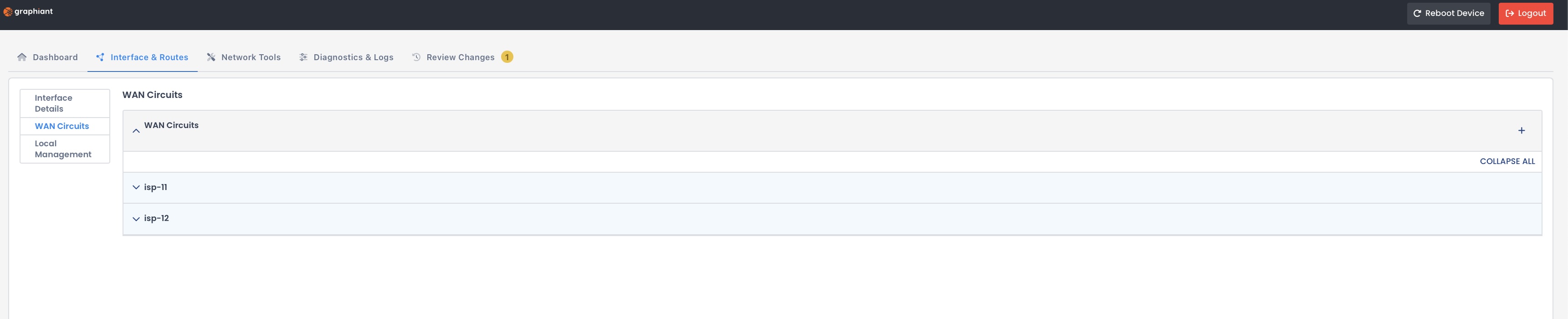
WAN Circuits
The WAN Circuits page shows:
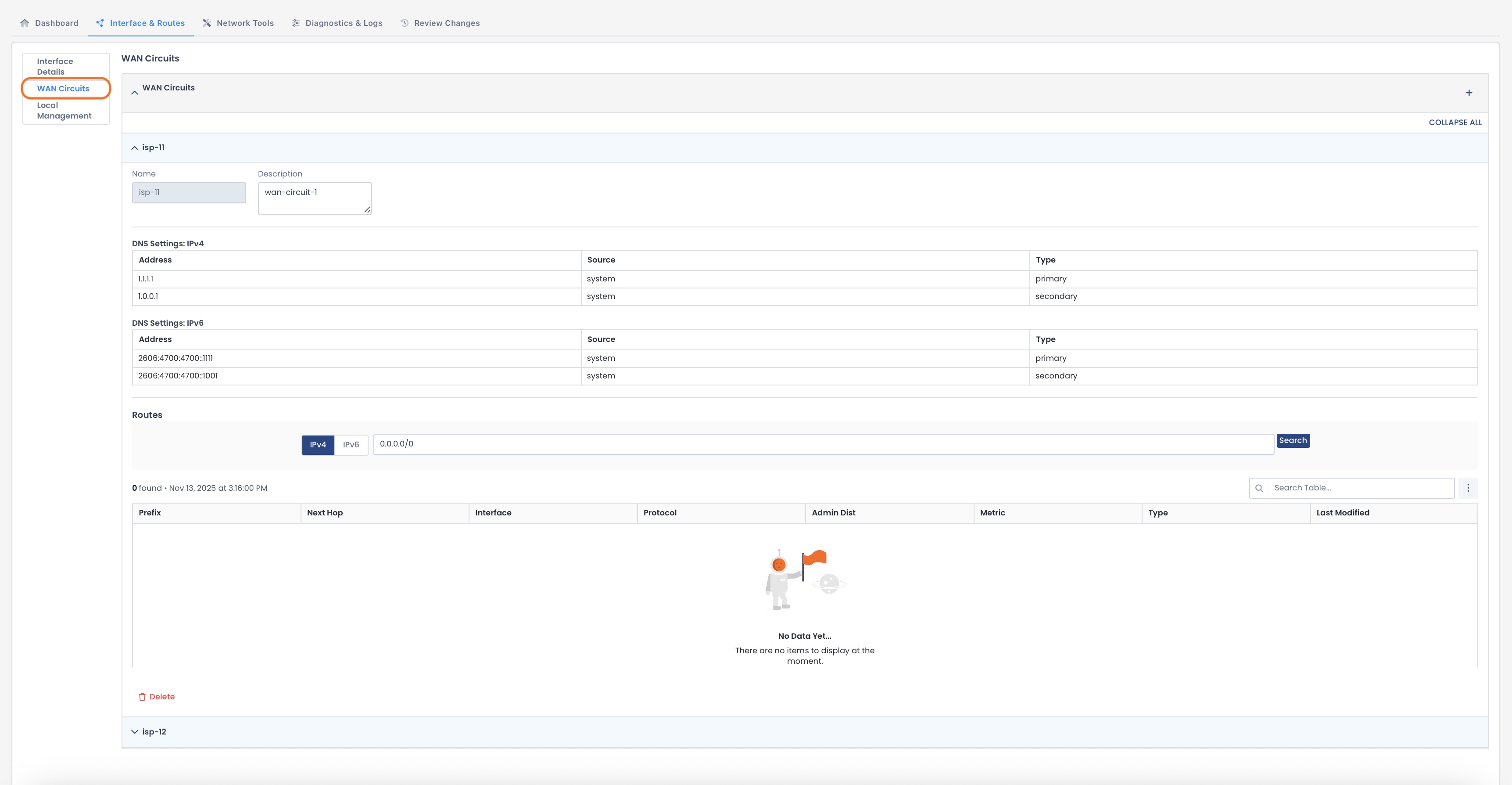
WAN Circuit Details
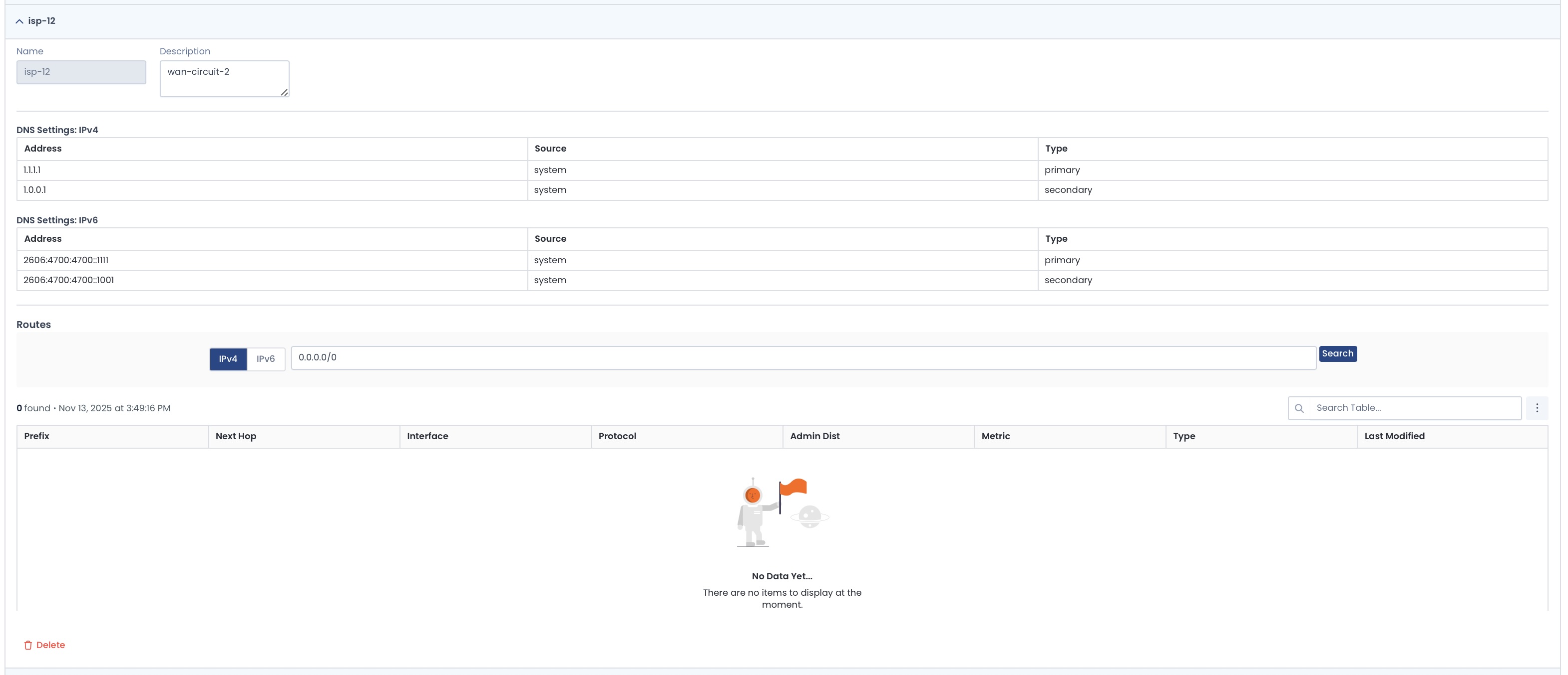
Any WAN Circuit’s details are visible by opening the carat next to the desired WAN Circuit.
Here you will see:
Name: Assigned name of the WAN Circuit
Description (editable): Your description of the WAN Circuit for ease of reference
DNS Settings (both IPv4 & IPv6):
Address: Destination address of the DNS server
Source: Origination of the WAN Circuit configuration
Type: Primary or Secondary
Route Information:
Prefix: Destination network/subnet for the route
Next Hop: IP address of the gateway or device to which the traffic is sent
Interface: That the route is utilizing.
Protocol: How the route was learned (static or dynamic)
Admin Distance: Priority value; lowest numbers take precedence
Metric: Decides the best path when multiple routes to the same destination are available
Type: Connected, static, or learned from another router
Last Modified: Date/Time the route configuration was last updated
Adding a WAN Circuit
To add a WAN Circuit, click the [+] at the top right of the WAN Circuit section.
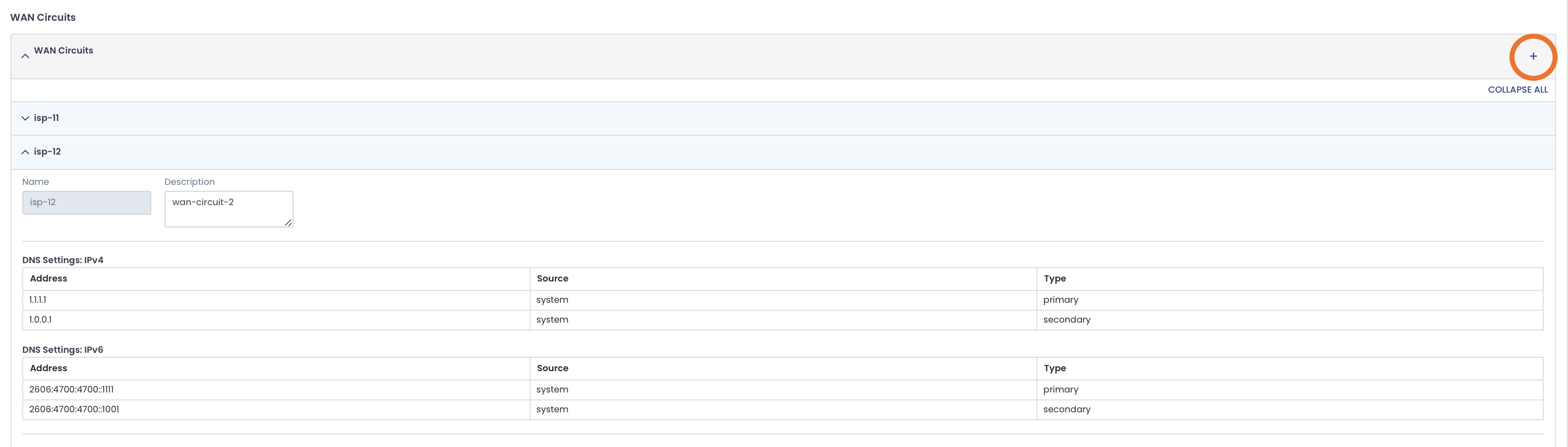
The new WAN Circuit will be created with the next number in the series.
WAN Circuit Numbering System:
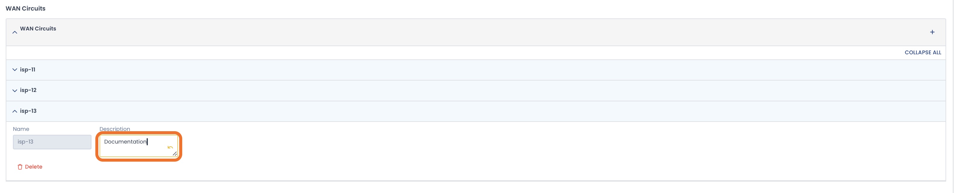
Graphiant begins the WAN Circuit numbering with the circuits embedded on the Edge as isp-11 and isp-12; any subsequent WAN Circuits will be numbered sequentially with “isp-13”; “isp-14”; “isp-15”, and so on.
If desired, enter a description for your reference.
Follow the instructions for reviewing and applying changes.
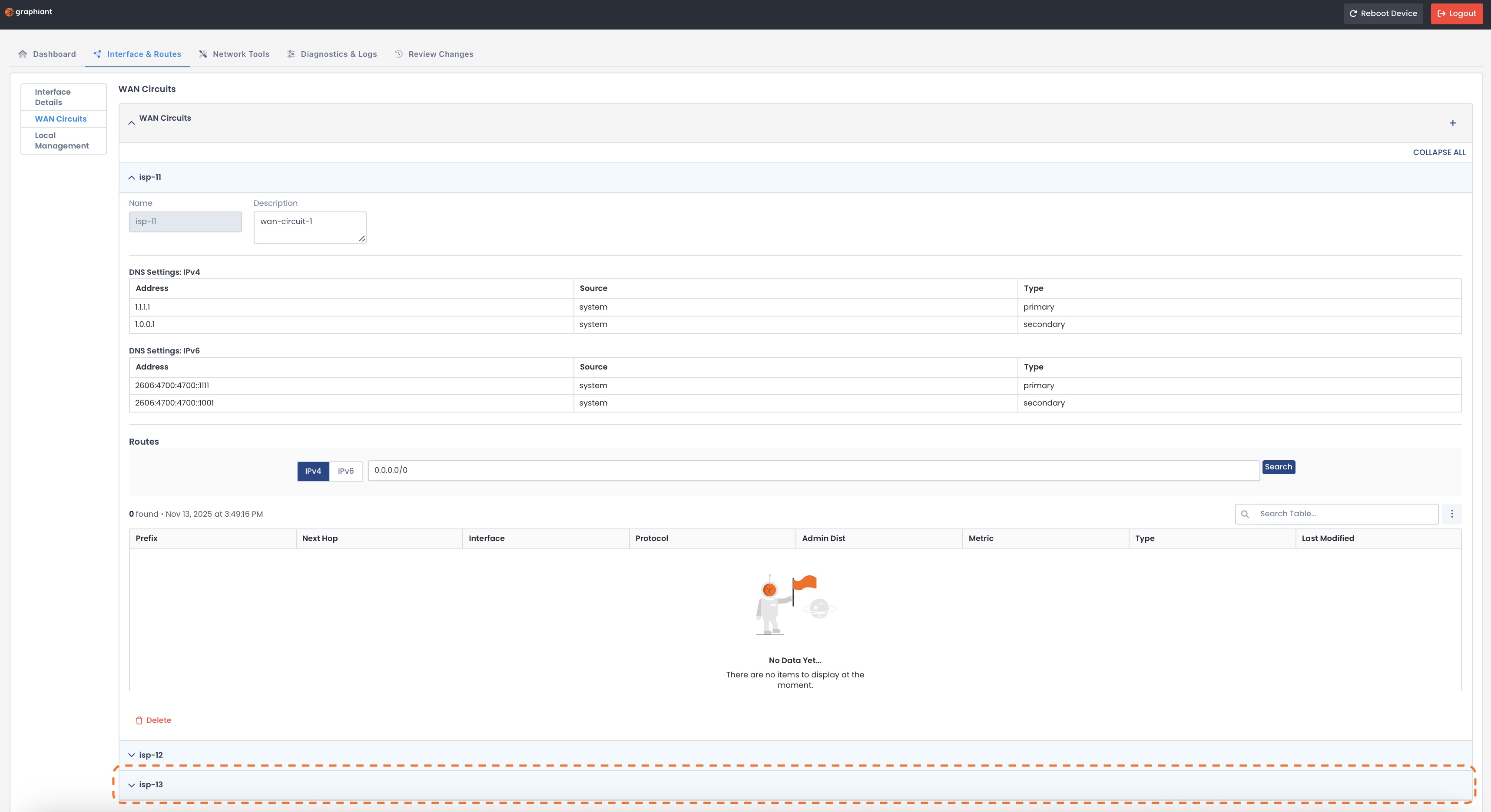
The new WAN Circuit will be configured and on your Edge; it will be added to the WAN Circuit page underneath the previous WAN Circuits.
Deleting a WAN Circuit
To delete a WAN Circuit, click the Delete icon at the bottom of the desired WAN Circuit.
.jpg)
The WAN Circuit will no longer appear on the page.
Follow the instructions for reviewing and applying changes.
The WAN Circuit will be deleted from your Edge.
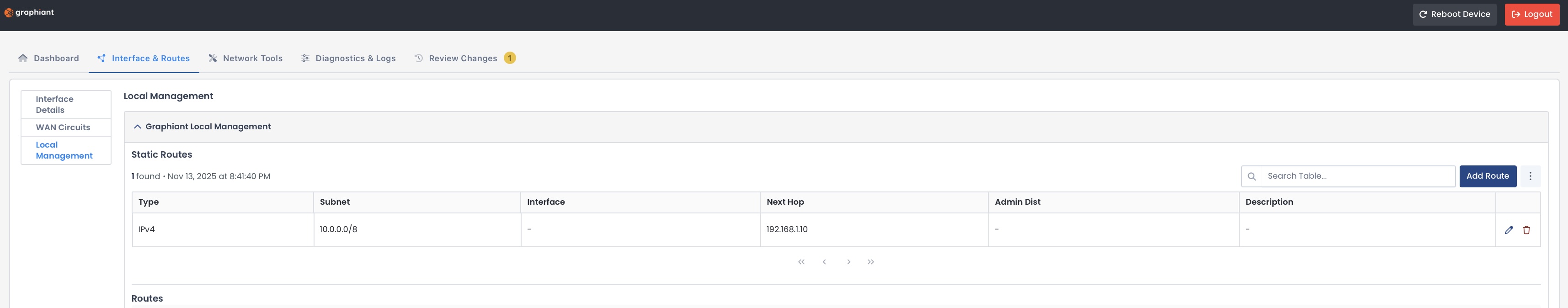
Local Management
This page houses the route information and configuration for the local management level, including:
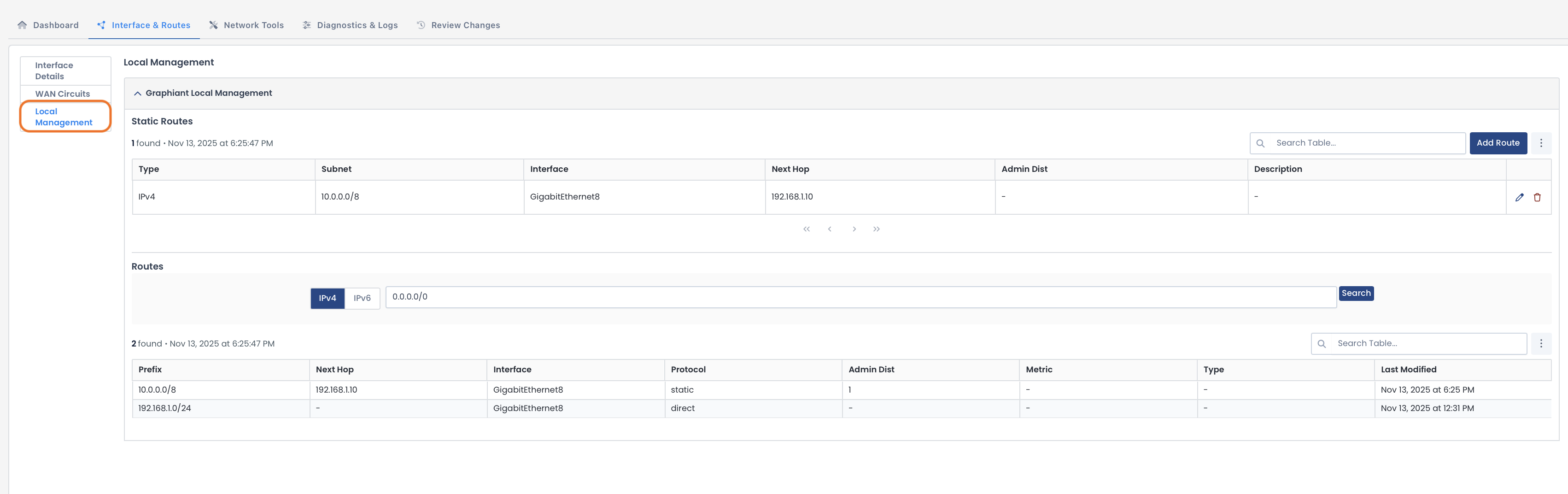
Static Route Table
This table shows the information for routes you have added manually:
Type: IPv4 / IPv6
Subnet: Remote network with which you are communicating
Interface: That the route is utilizing
Next Hop: IP address of the gateway or device to which the traffic is sent
Admin Distance: Priority value; lowest numbers take precedence
Description: Your description of the interface for ease of reference
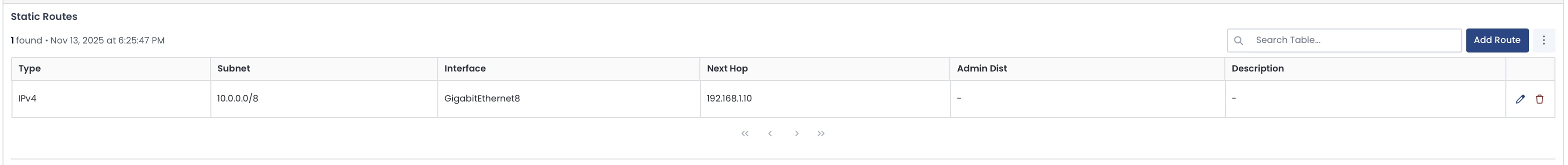
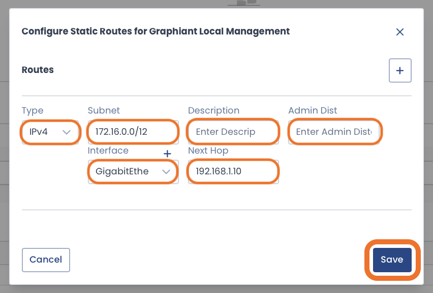
Adding a Static Route
To add a Static Route to your local management interface, click ‘Add Route’ at the top right of the Static Route table.

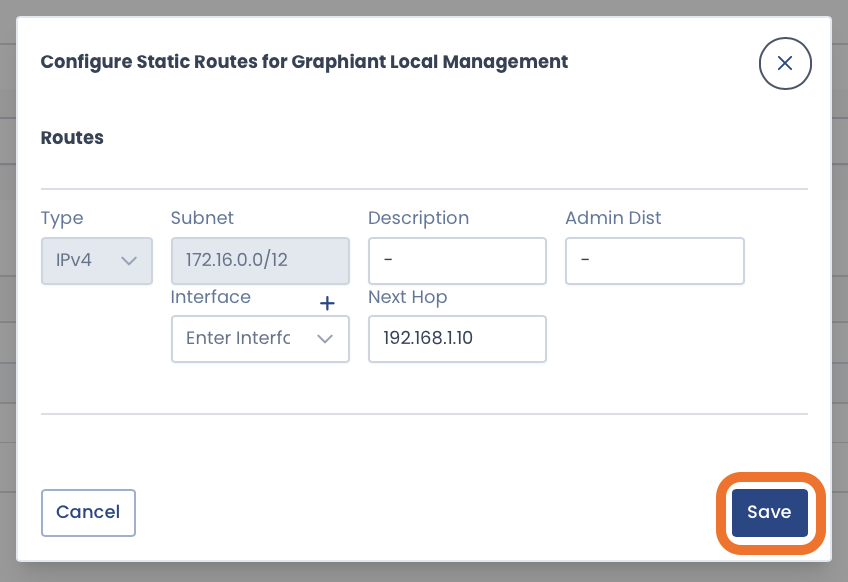
Complete the following fields:
Type: IPv4 / IPv6
Subnet: Remote network with which you are communicating
Description: Your description of the interface for ease of reference
Admin Distance: Priority value; lowest numbers take precedence
Interface: That the route is utilizing
Next Hop: IP address of the gateway or device to which the traffic is sent
For your convenience:
Additional routes can be added without leaving the modal by clicking the [+] button.
Click ‘Save’.
The new route information will appear in the table.

Follow the instructions for reviewing and applying changes.
Warning:
Your new static route(s) is only temporarily active for 2 minutes; a banner message will appear regarding this.
Review the configuration, and ensure that the route you have configured is correct.
A ‘Confirm Apply’ button will become available in 30 seconds; click ‘Confirm Apply’ when it is active.
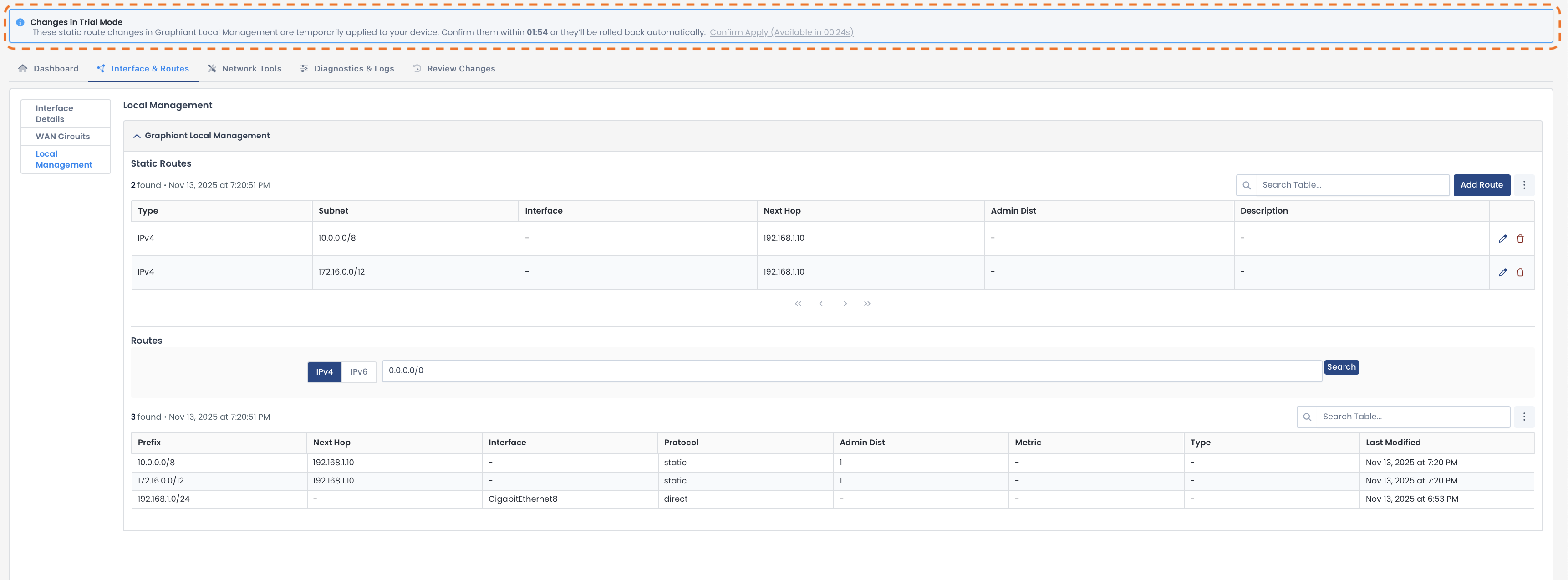
Click ‘Confirm Apply’ to permanently save your static route(s).

The new static route is now confirmed and included in both tables.
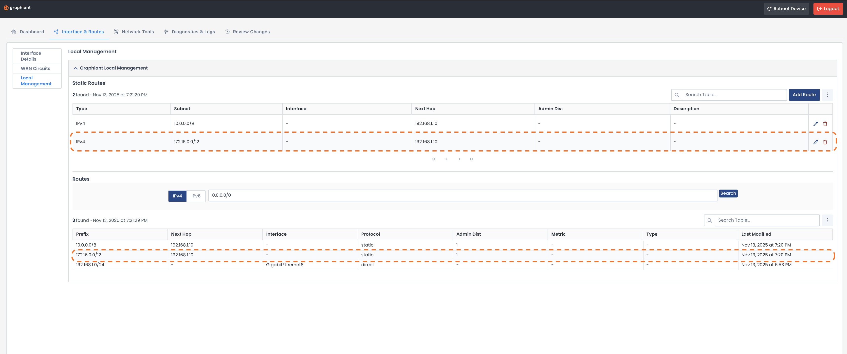
Editing a Static Route
To edit a Static Route on your local management interface, click the pencil icon to the right of the desired route.

Edit the desired fields.
Click ‘Save’.
Follow the instructions for reviewing and applying changes.
The static route will be updated on your local management interface.
Deleting Static Routes
To edit a Static Route on your local management interface, click the delete icon to the right of the desired route.
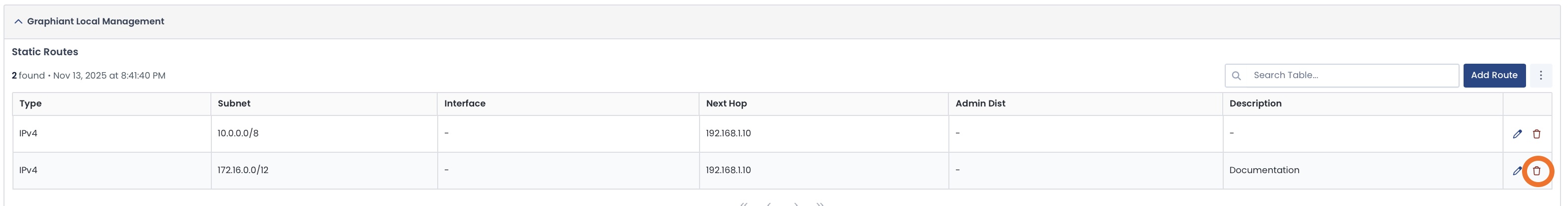
The Static Route will no longer appear in the table.
Follow the instructions for reviewing and applying changes.
The static route will be deleted from your local management interface.
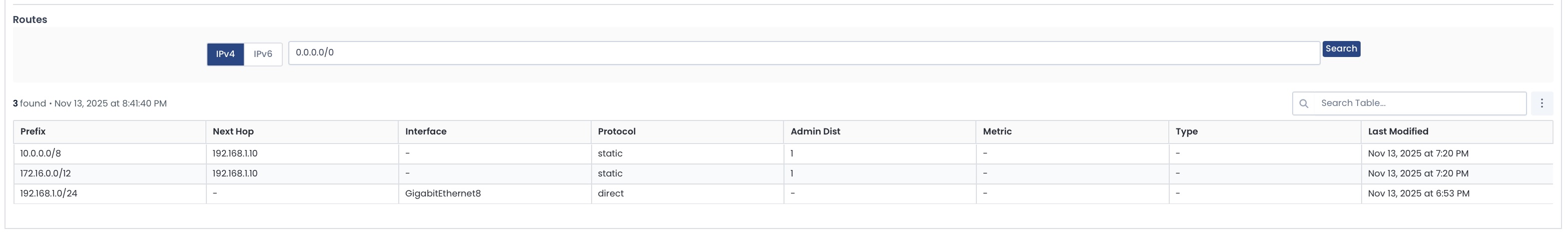
Route Table
The Route Table shows information for all known routes by your local management interface, including:
Prefix: Destination network/subnet for the route
Next Hop: IP address of the gateway or device to which the traffic is sent
Interface: That the route is utilizing
Protocol: How the route was learned (static or dynamic)
Admin Distance: Priority value; lowest numbers take precedence
Metric: Decides the best path when multiple routes to the same destination are available
Type: Connected, static, or learned from another router
Last Modified: Date/Time the route configuration was last updated
Review Changes
Any configuration changes will need to be reviewed, then applied to your Edge.
The number of changes will be in yellow next to the “Review Changes” tab.
Click the ‘Review Changes’ tab.
Changes will appear as follows:
Green: Item added to the configuration
Yellow: Edit to the configuration
Red: Item deleted from the configuration
Confirm that your changes are correct.
Click ‘Apply Changes’.

The new configuration will be set and on your Edge, and the Edge will be visible and connected to the Graphiant Portal.
Follow the process in Onboarding Your Graphiant Edge to complete the onboarding of your Edge in the Graphiant Portal.
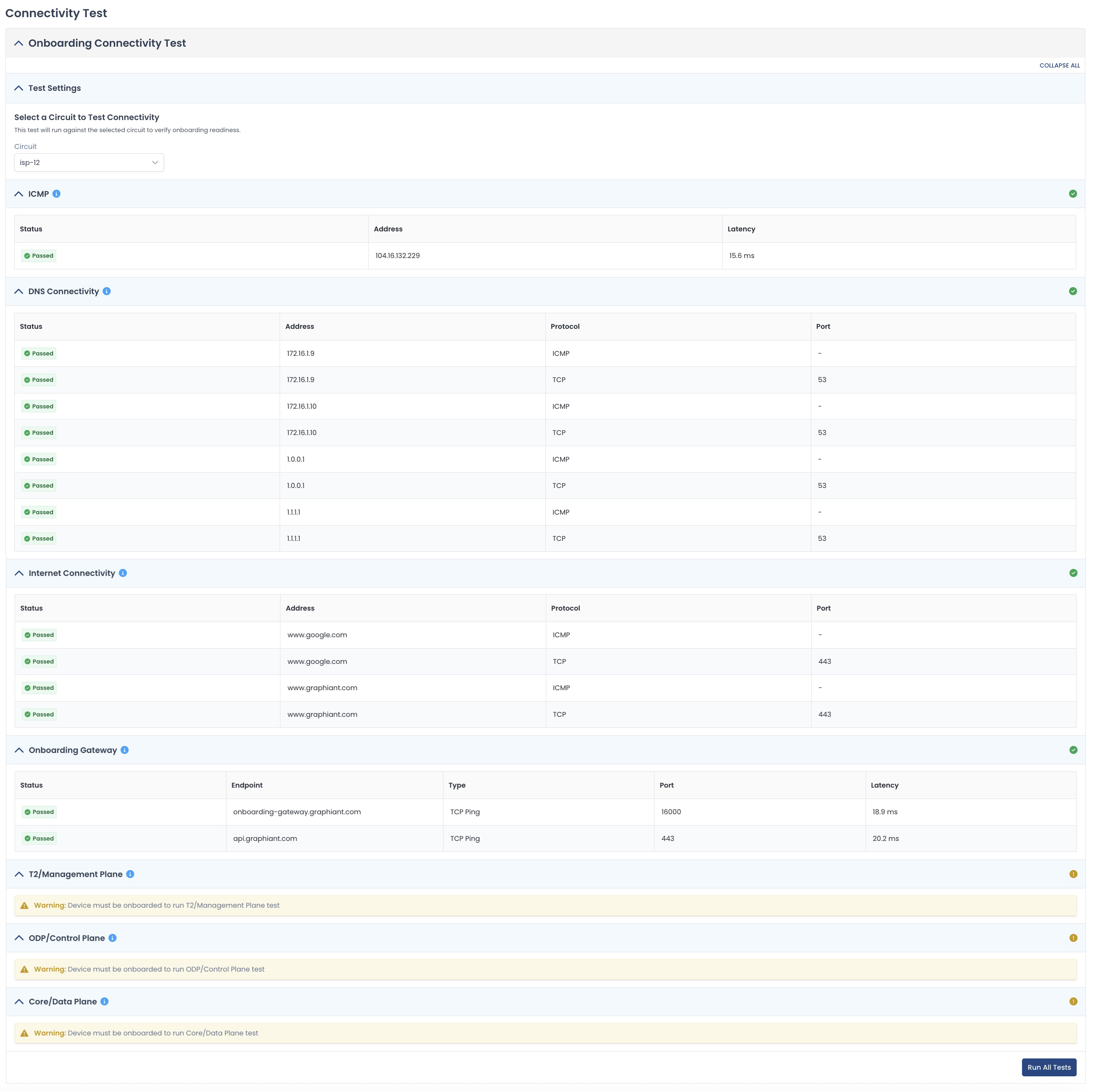
Checking Connectivity
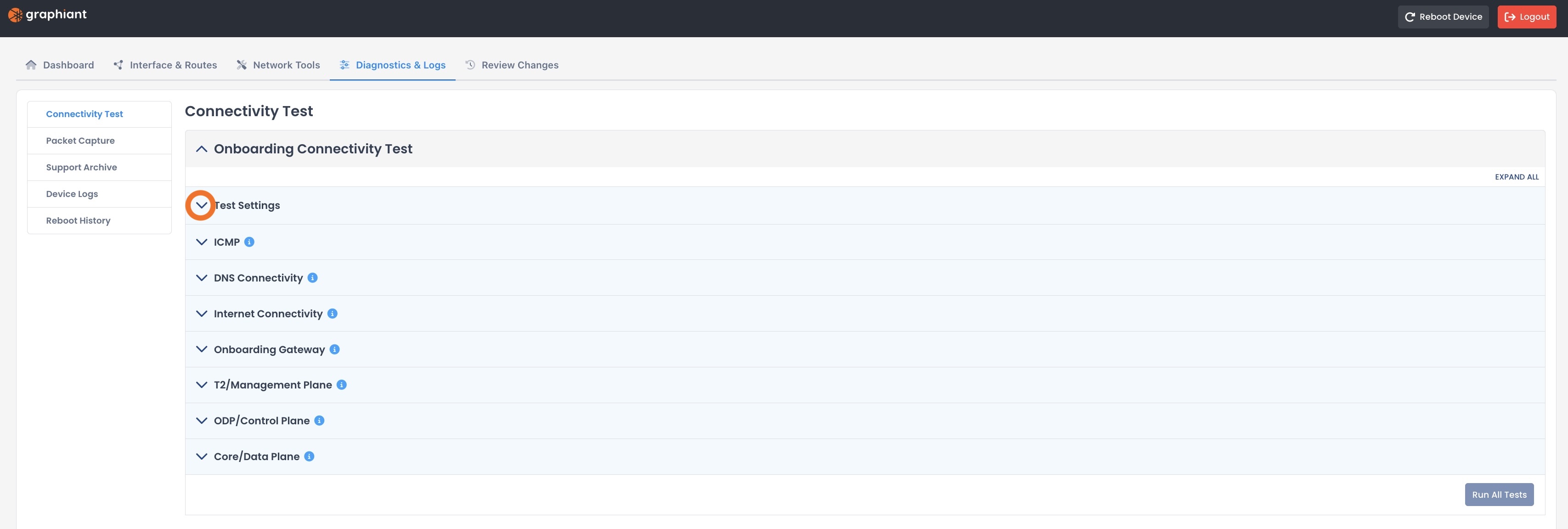
To check the connectivity of your edge via the local web server, navigate to the ‘Diagnostics & Logs’ tab.
This will open the Diagnostics & Logs landing page.
.jpg)
Click the carat for Test Settings.
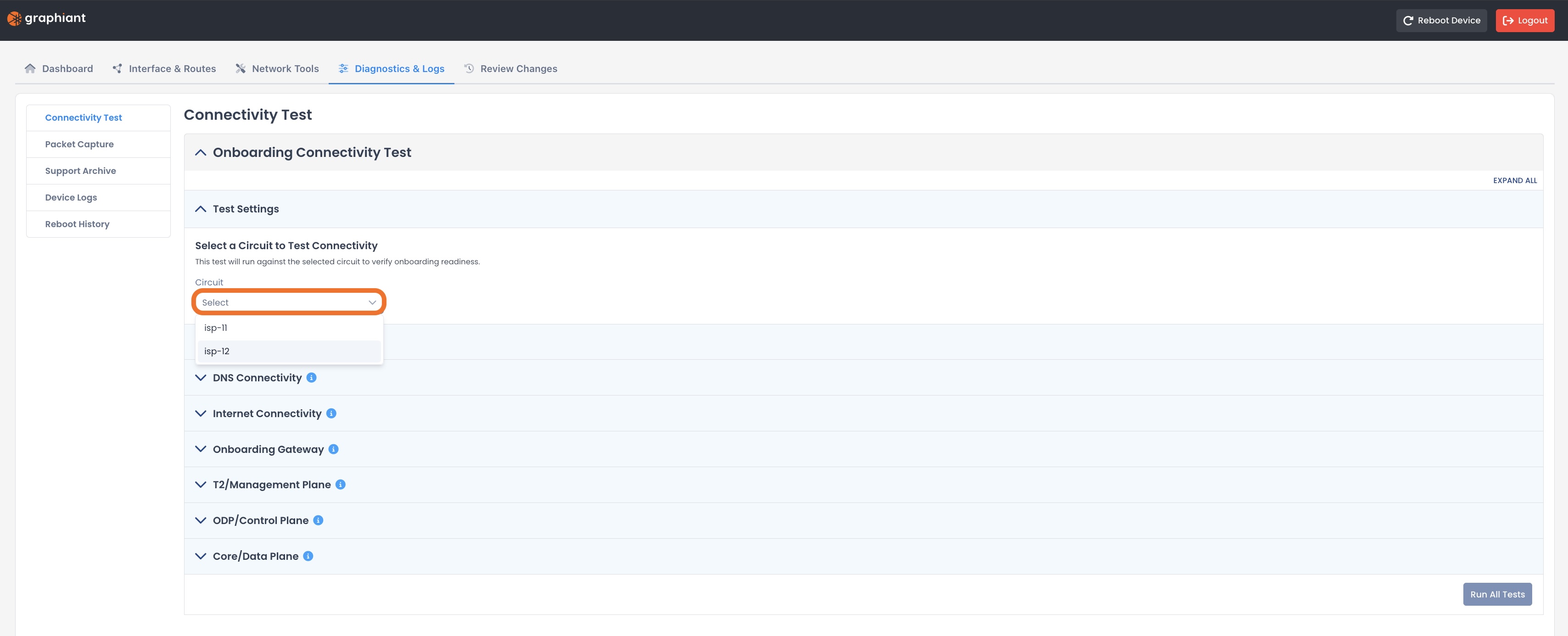
Select the circuit that you wish to test.
Note:
By default:
isp-11 is assigned to the first WAN interface
isp-12 is assigned to the second WAN interface
Click ‘Run All Tests’.
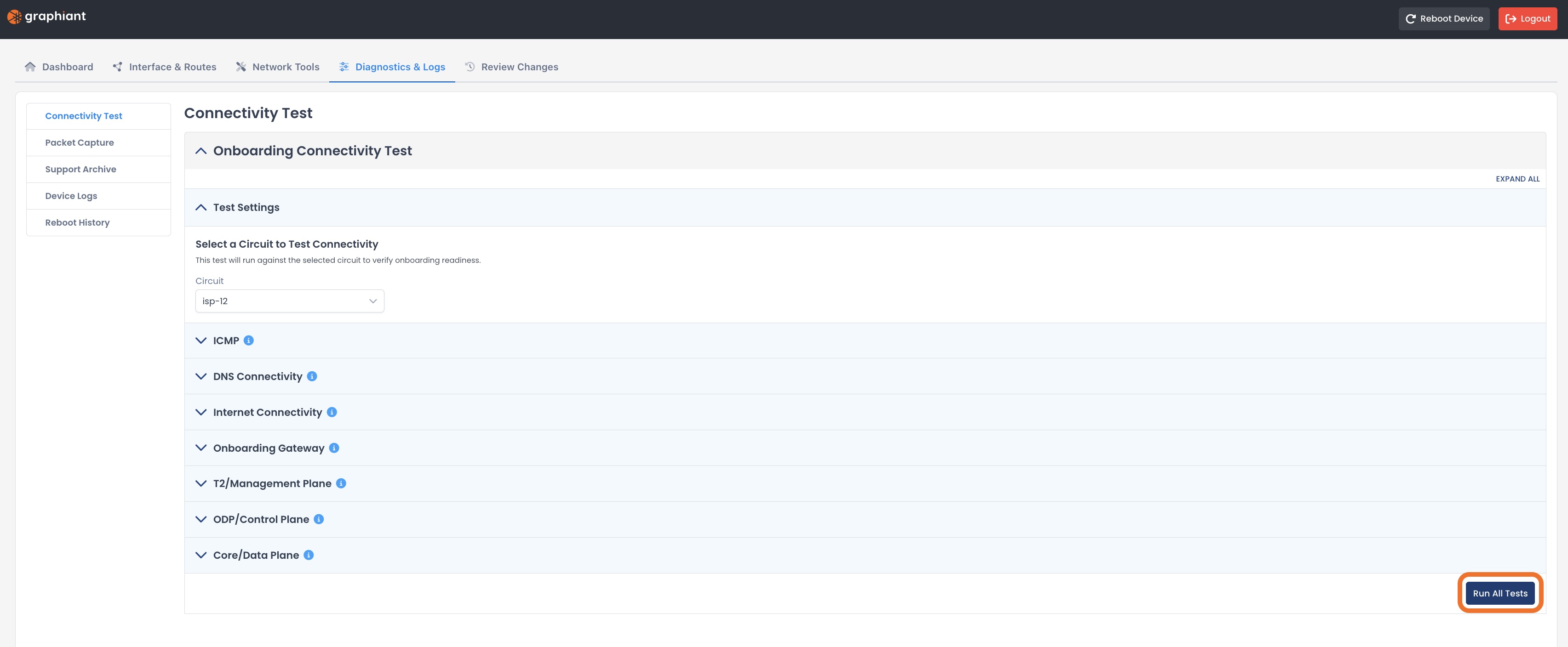
The specific test results will be shown under each test.
Note:
The bottom three tests will not have results until the device is onboarded in the Graphiant Portal.