The interfaces of a Graphiant Edge router can be classified into two groups, WAN and LAN interfaces.
WAN interfaces are used to connect to the internet and are used by the Edge to establish management, control and data plane connections.
LAN interfaces are used to connect to the local network in the enterprise location, and may be used to run routing protocols such as BGP and OSPF in more complex environments or use static routes in simple environments locations.
Types of interfaces
The Graphiant Edge currently supports 4 different types of interfaces:
Ethernet: an L3 routed interface that supports both IPv4 and IPv6
Subinterface: a virtual L3 interface that supports VLAN tagging
Loopback: a virtual loopback interface
IPsec: a virtual interface that can be used to create IKE based IPsec tunnels with 3rd party devices
Interfaces in the Graphiant Portal
From within the Graphiant Portal, you will be able to configure interfaces on an edge.
Step 1: Locating interfaces in the Graphiant Portal
From the Home screen, navigate to the Edge Configuration screen by one of the following:
Locate the "Configurations" section within the “Quickstart” area of the screen; select 'Configure Edges'.
or
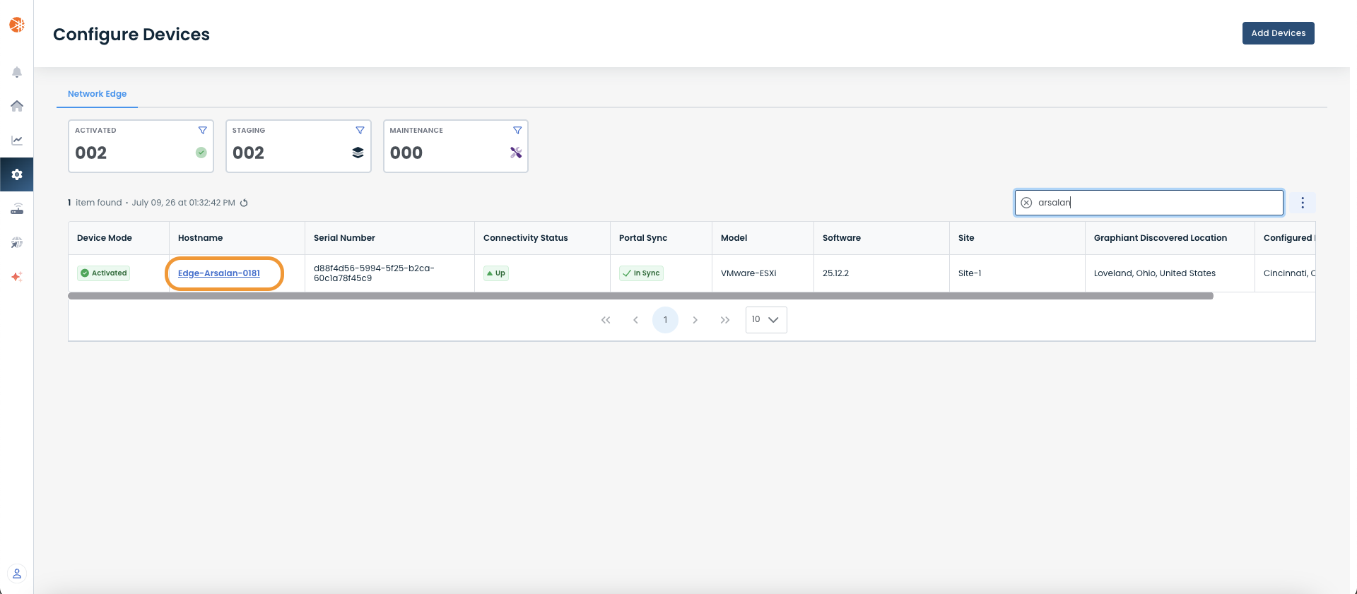
Click 'Configure' in the sidebar; select 'Devices'.
.png)
This will take you to the ‘Configuration’ page of the Graphiant Portal where you can view all active, staged, and deactivated Edges. From here you will be able to select among the active Edges which Edge(s) you would like to configure.
On the right hand side, select and click ‘Configure’ in tandem with the Edge you wish to manage.
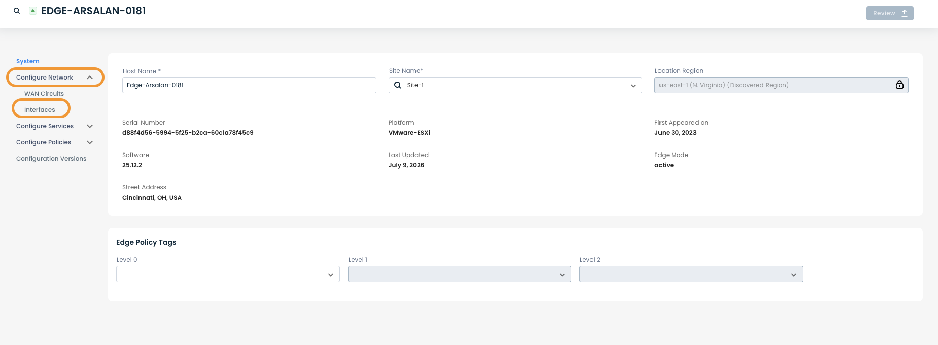
This will take you onto a Configuration page with a focus on the Edge you have just chosen.
Here you will see a list of headers along the left hand side of the page, such as ‘Configure Network’, ‘Configure Services’, ‘Configure Policies’, etc.
From here, select and click ‘Configure Network’; and from the dropdown menu, select and click ‘Interfaces’.
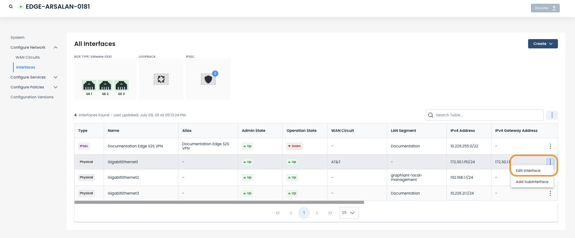
On the Interfaces page, you will see a list of available interfaces to choose from. This list includes all physical as well as virtual interfaces.
You can also create new virtual interfaces from this view.
.png)
Step 2: Setting up interfaces in the Graphiant Portal
Step 2a: Setting up an ethernet interface
On the Interfaces page select the interface you want to configure by clicking the 3 dots to the right of the interface and choosing "Edit Interface".
The interface can be configured in two different modes, WAN or LAN. This mode determines what capabilities are available on the interface.
WAN Mode
Off/On: Toggle to disable/enable the interface
Interface Name: User defined name to use for the interface, when this name is changed all other configuration and monitoring views are updated to use the new name
Interface Description: User defined description to assign to this interface
Interface Type: Mode in which this interface should operate, WAN or LAN (select WAN)
WAN Circuit: The WAN circuit to which this interface should be attached (learn how to configure a WAN Circuit)
IPv4: The IPv4 address configuration to use for this interface, DHCP or Static.
Static: If static is selected you will need to enter:
The IP address and prefix length for the interface (e.g: 192.168.100.2/24)
The IP address for the Gateway (e.g: 192.168.100.1)
IPv6: The IPv6 address configuration to use for this interface, DHCP or Static.
Static: If static is selected you will need to enter:
The IP address and prefix length for the interface (e.g: fe00::1/64)
The IP address for the Gateway (e.g: fe00::2)
Interface Advanced Settings:
MTU: The Maximum Transmission Unit value to use for the interface.
Note:
Interfaces support dual stacking IPv4 and IPv6.
If you do not want to configure an interface to be dual stacked (instead run in IPv4 or IPv6 only), then you can set the relevant version to static and leave the IP address & Prefix length box empty.
.png)
LAN Mode
Off/On: Toggle to disable/enable the interface
Interface Name: User defined name to use for the interface; when this name is changed all other configuration and monitoring views are updated to use the new name
Interface Description: User defined description to assign to this interface
Interface Type: Mode in which this interface should operate, WAN or LAN (select LAN)
LAN segment: The LAN segment of which this interface should be a part. This field provides a dropdown containing all the existing LAN segments in your network; it also allows you to use a new LAN segment (a LAN segment that doesn't currently exist in the network).
Create a new LAN segment: To create a new LAN segment you need configure an interface to reference a new LAN segment; this will automatically create the LAN segment in our system. To do this, enter the name of the new LAN segment in the “LAN Segment” field and press ‘Enter’. When you apply these changes to the device, the LAN segment will be automatically created; it will then appear in the “LAN Segment” dropdown for all other interfaces of this and other Edges.
Delete a LAN segment: To delete a LAN segment you need to detach every Edge from the LAN segment; this will automatically delete the segment from our system.
IPv4: The IPv4 address configuration to use for this interface: DHCP or Static.
Static: If static is selected you will need to enter the IP address and prefix length for the interface (e.g: 192.168.100.2/24).
IPv6: The IPv6 address configuration to use for this interface: DHCP or Static.
Static: If static is selected you will need to enter the IP address and prefix length for the interface (e.g: fe00::1/64).
VRRP: Visit the Configure VRRP page to learn how to setup VRRP.
DHCP Relay: Visit the Configure DHCP Relay page to learn how to set this up .
Interface Advanced Settings:
MTU*: The Maximum Transmission Unit value to use for this interface
MSS*: The TCP Maximum Segment Size value to use for this interface
LLDP*: Toggle to disable/enable LLDP on this interface; defaults to off.
Note:
Interfaces support dual stacking IPv4 and IPv6.
If you do not want to configure an interface to be dual stacked (instead run in IPv4 or IPv6 only) then you can set the relevant version to static and leave the IP address & Prefix length box empty.
MTU, MSS and LLDP configurations are only valid for physical Ethernet interfaces; they do not apply to subinterfaces.
.png)
Step 2b: Setting up a Subinterface
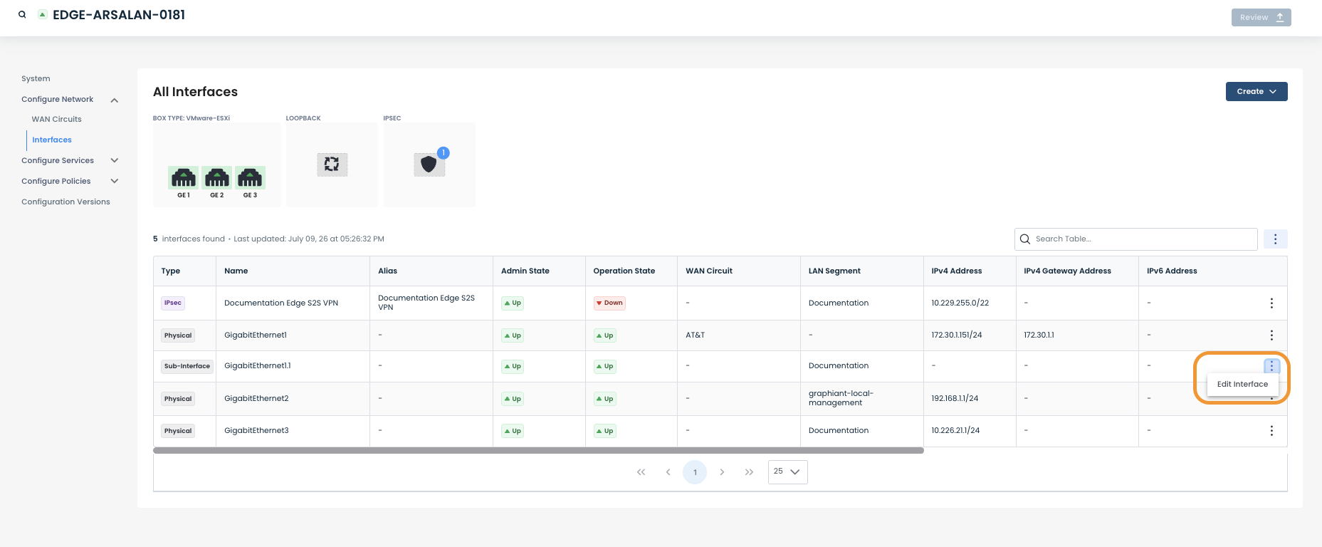
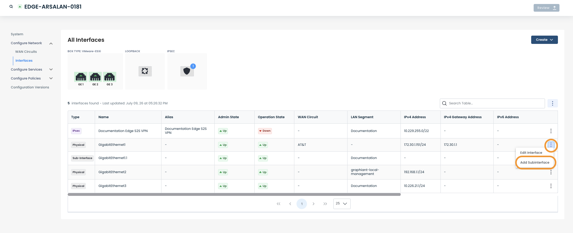
To configure an existing subinterface, on the Interfaces page, click the 3 dots to the right of the interface and choose "Edit Interface".
To create a new subinterface, select ‘Add Subinterface’ after clicking the 3 dots to the right of the interface which you want to associate with the subinterface.
A subinterface supports configuring a VLAN ID to define which VLAN it belongs to. To configure the interface as a trunk port use VLAN ID 0.
All remaining configurations for a subinterface are the same as an ethernet interface. Please reference 'Step 2a: Setting up an ethernet interfaces' for details on how to configure the other capabilites.
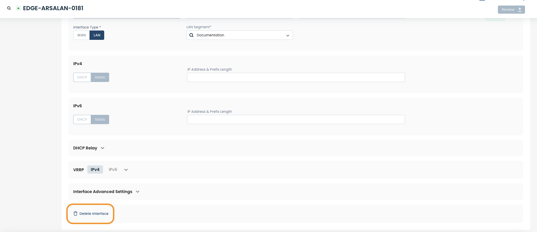
To delete a subinterface, select the relevant interface; scroll down to the bottom of the interface configuration view and click ‘Delete Interface’.
Step 2c: Setting up a loopback interface
To configure an existing loopback, on the interfaces page, click the 3 dots to the right of the interface you want to configure and select 'Edit Interface'.
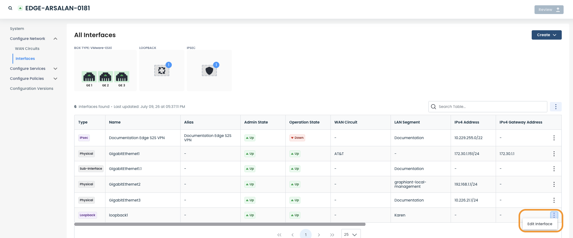
To view existing loopbacks, click on the ‘Loopback’ icon.
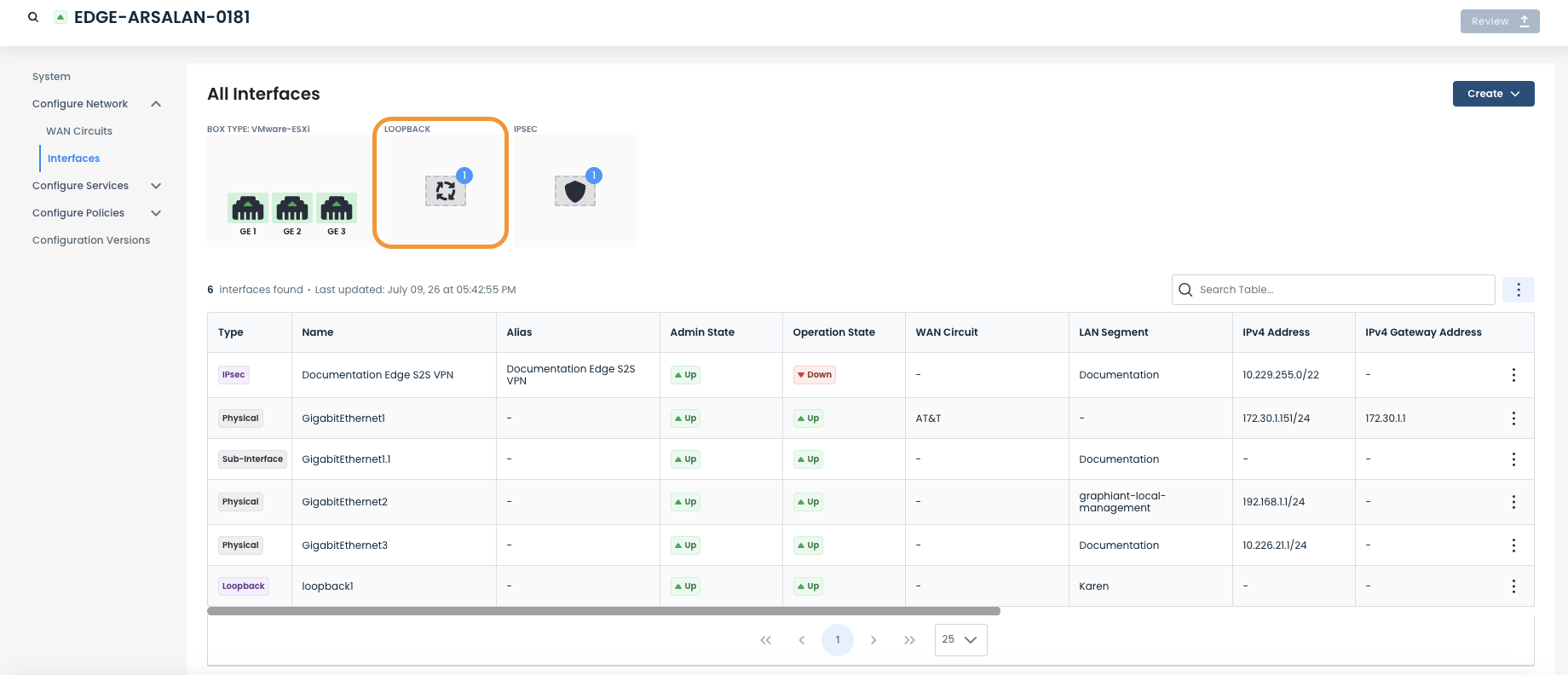
You will see a new view, displaying only loopback interfaces.
.png)
To create a new loopback, on the right-hand side, click ‘Create’ and a dropdown menu will appear. Click ‘Loopback’.
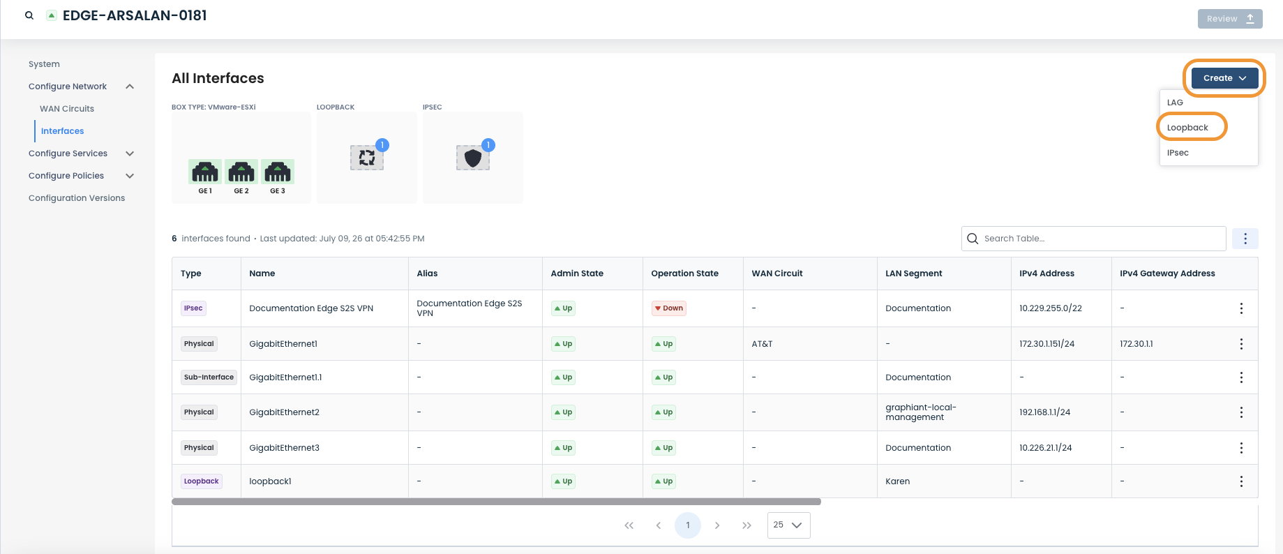
You will see a new configuration view; you can now configure the new loopback interface.
.png)
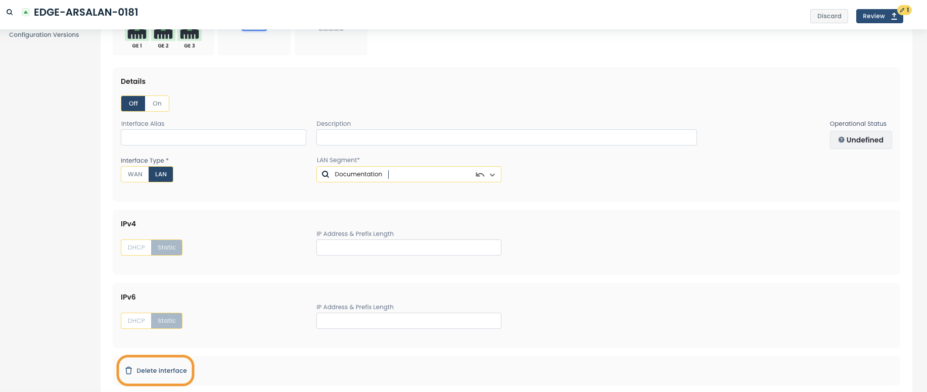
LAN Mode
Note:
Loopback interfaces only support LAN mode.
Off/On: Toggle to disable/enable the interface.
Interface Name: User defined name to use for the interface; when this name is changed all other configuration and monitoring views are updated to use the new name.
Interface Description: User defined description to assign to this interface
LAN segment: The LAN segment of which this interface should be a part. This field provides a dropdown containing all the existing LAN segments in your network; it also allows you to use a new LAN segment (a LAN segment that doesn't currently exist in the network).
Create a new LAN segment: To create a new LAN segment, you need configure an interface to reference a new LAN segment; this will automatically create the LAN segment in our system. To do this enter the name of the new LAN segment in the “LAN Segment” field and press enter. When you apply these changes to the device, the LAN segment will be automatically created; it will then appear in the “LAN Segment” dropdown for all other interfaces of this and other Edges.
Delete a LAN segment: To delete a LAN segment, you need to detach every Edge from the LAN segment; this will automatically delete the segment from our system.
IPv4: The IPv4 address configuration to use for this interface: DHCP or Static.
Static: If static is selected you will need to enter the IP address and prefix length for the interface (e.g: 192.168.100.2/24).
IPv6: The IPv6 address configuration to use for this interface: DHCP or Static.
Static: If static is selected you will need to enter the IP address and prefix length for the interface (e.g: fe00::1/64).
Note:
Interfaces support dual stacking IPv4 and IPv6.
If you do not want to configure an interface to be dual stacked (instead run in IPv4 or IPv6 only) then you can set the relevant version to static and leave the IP address & Prefix length box empty.
To delete a loopback interface, select the relevant interface; scroll down to the bottom of the interface configuration view and click ‘Delete Interface’.
Step 2d: Setting up an IPsec interface
An IPsec interface is a special kind of virtual interface meant to be used to create IKE based IPsec tunnels with 3rd party devices.
Configuring MACsec
Graphiant offers MACsec as an additional layer of point-to-point security for your ethernet links.
MACsec is supported only for dedicated physical connections between the gateway and the cloud:
The connection cannot be a shared or hosted connection.
If a physical port is not available, Graphiant may need to deploy additional hypervisors. If that is the case, please contact your sales team; they will share the ETA once your request is submitted.
MACsec will need to be configured on your cloud provider first.
For information on this process for the different providers, see:
Google (GCP): https://docs.cloud.google.com/network-connectivity/docs/interconnect/concepts/macsec-overview
https://docs.cloud.google.com/network-connectivity/docs/interconnect/how-to/macsec/set-up-macsec
Amazon (AWS): https://docs.aws.amazon.com/directconnect/latest/UserGuide/MACsec.html
Microsoft Azure: https://learn.microsoft.com/en-us/azure/expressroute/expressroute-howto-macsec
Oracle (OCP): https://www.ateam-oracle.com/how-to-configure-macsec-in-oci
When in the configuration page for interfaces, open the carat next to “MACsec Configuration”.
.png)
This will open the configuration fields for MACsec.
By default MACsec is toggled off.
.png)
Toggle on to “MACsec Enabled”, and the fields will be able to be configured.
.png)
Note:
Currently, only “Must Encrypt” is offered by Graphiant, so that encryption is strictly enforced.
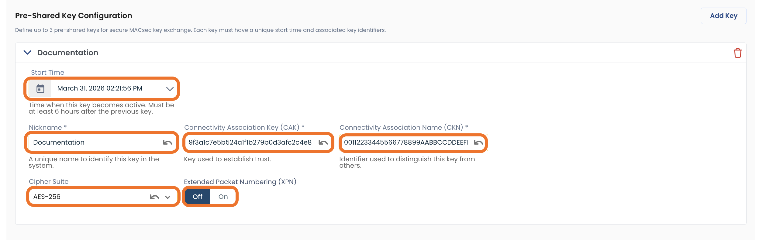
Pre-Shared Keys
Graphiant supports up to three Pre-Shared Keys, so there is no concern about key rotation.
To add a Pre-Shared Key, click ‘Add Key’.
‘Note:
Up to three Pre-Shared Keys can be entered for secure key exchange.
Each key must have unique start times and associated key identifiers.
.png)
Fill out the following fields:
Start Time: Time that the key will be active; must be 6 hours or more after the previous key.
Nickname: Your internal assigned name of this key for quick reference
Connectivity Association Key: The pre-shared encryption key used to secure the MACsec connection between peers
Connectivity Association Name: A shared identifier that associates the pre-shared key with a MACsec connection. Must match on both peers.
Cipher Suite: Specifies the encryption algorithm and key length used to secure MACsec traffic.
Extended Packet Numbering: Indicates whether an extended packet number range is used to support long-lived, high-throughput encrypted sessions
Add up to two more Pre-Shared Keys as desired by clicking ‘Add Key’ again.
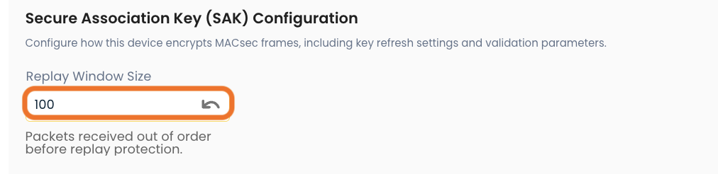
Secure Association Key
The settings for how this device encrypts MACsec frames.
Complete the following fields:
Replay Window Size: Number of packets that can be accepted out of order to protect against replay attacks while maintaining traffic flow
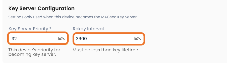
Key Server Configurations
These settings are only used when this device becomes the MACsec Key Server.
Complete the following fields:
Replay Window Size: Number of packets that can be accepted out of order to protect against replay attacks while maintaining traffic flow
Key Server Priority: Determines which device acts as the MACsec key server; the device with the lowest priority is selected.
Rekey Interval: How often the MACsec encryption keys are refreshed to maintain security
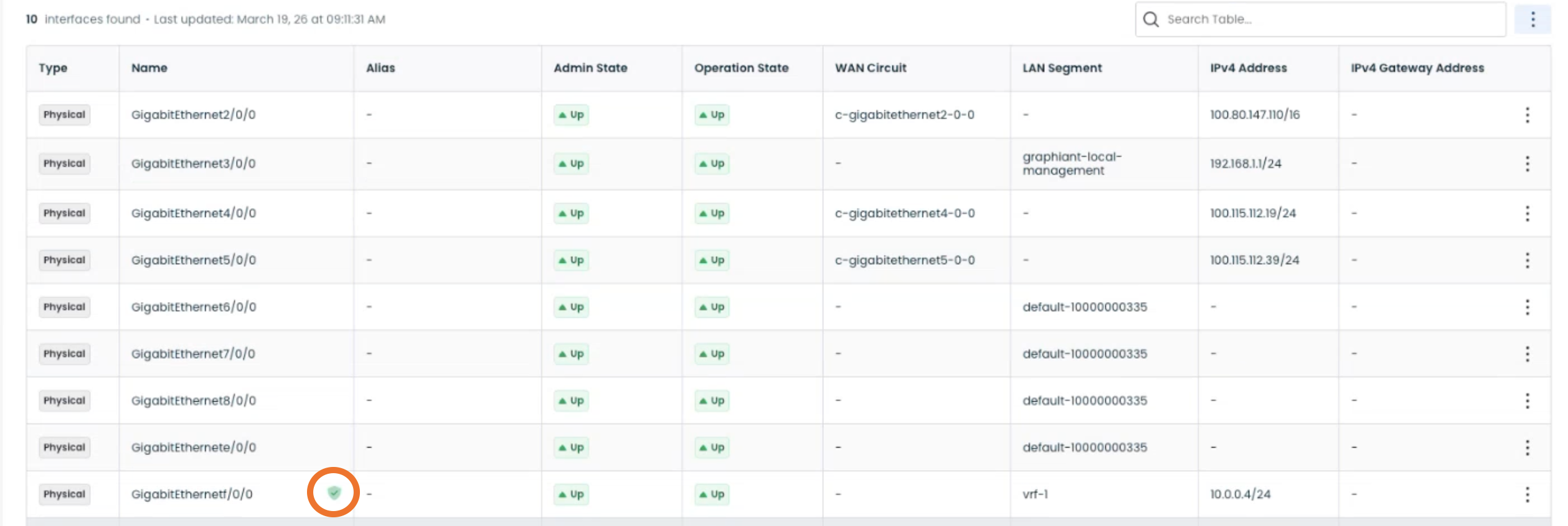
Note:
When an interface is configured with MACsec, it will have a shield icon next to the interface name in the table.
The shield will appear:
Green if the MACsec interface is up
Amber if the MACsec interface is down
Step 3: Review & Apply
Once the above fields are filled in, the selected Edge interface(s) will be ready to use; however you will first need to review and approve all changes made.

On the top right hand corner, choose from the following options:
‘Discard’ to discard changes made.
‘Save as Draft’ to save changes made to be implemented at a later time.
‘Review’ to review and apply changes made for immediate deployment.